
The Power Plant
Firing-up a rebuilt engine and hearing it run smoothly is one of life's gretest experiences. It took a few tries with my first one, but after resolving carburetor, compression, and spark voltage issues - it now runs great!
The Block
If you're like me, you can take anything apart. Putting stuff back together: that's the tricky part. About the only special tool required for engine block work is the handy-dandy "Old Hokie" sleeve removal tool. It's also of incredible value for installing new sleeves. Dan the "Old Hokie" also provided great email support and tips: I'd like to meet him someday and thank him in person for his products and kind post-sales support.
http://mysite.verizon.net/oldhokie/windyridge/id5.html
Once I had the block clear of all removable parts, I cleaned it using decades old electrolysis. It requires a 12V battery charger to supply power (very little current draw) and a 12V battery to ensure pure DC current flow (like a big filter capacitor). You will also need sodium carbonate: go to Walmart and get some Arm & Hammer super washing soda. Do NOT use baking soda! I rigged this simple setup in a big plastic Tupperware bin: positive (red) on the outside electrodes and negative (black) connections to the block.
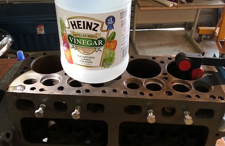
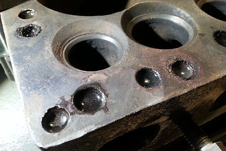
After you filter out the crud and rust, keep the electrolysis process going as this takes a few days. After a good water rinse, you'll have a nice clean block. A poor man's acid bath. Then I noticed a block water jacket around cylinder #4. Another economic solution: white vinegar. This took a few days, too. I put some white vinegar on the blocked intake & exhaust water jacket ports. It bubbled and cleared away the opening after a few days of freshly added vinegar.

Sleeves & Pistons
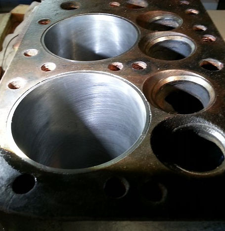
As mentioned above, I don't see how you can install new sleeves without Old Hokie's handy-dandy tooling. You should not need a tremendous amount of force to install the new sleeves. If they feel really tight, you may have to sand (or hone) the sleeve walls. Freezing the sleeves helps to reduce their diameter, too, to help aid installation. You don't want to crack or bend a brand-new sleeve.
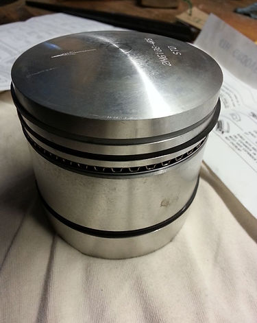
Take your time measuring each ring BEFORE installing the on the pistons. This involves placing them inside the cylinder and using a feeler gauge to check the gap. THEN you can install them on the new piston. I used a light coating of engine oil on the installed sleeve to help initial lubrication of the new piston & rings. Then you can attach the connecting rods, etc.
Valves
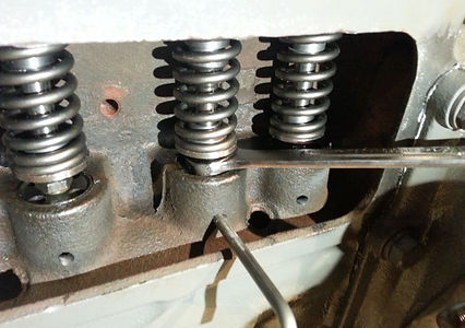
I replaced the valves and guides. The new 1-piece valve guides went in fine. I used coarse then fine lapping compound as shown in the left image. It all worked really well and I was quite happy with the valve seating when it was all done. Intake valve seals were added as shown to the right.
What I was not happy with was adjusting the valve tappets. The little wrench you can buy (or make) to hold the tappets stationary by anchoring the tool to a neighboring tappet... not a great approach. The tappets can be stiff to adjust and I grew tired of the anchoring tool slipping off. That said, I went ahead to popped holes into the block to manually insert a tappet holding shaft: works great.
The trick is to drill the holes WITHOUT getting ANY metal filings anywhere in the block. The solution was quite simple: place magnets, about 1" diameter, inside plastic bags and place the bags with the magnets inside into the valve guide opening. Also place some bagged magnets externally where you are drilling. I was absolutely delighted how well this worked: all the metal filings "marched in-line" right to the magnets.
Why the plastic bag? After you're done drilling, you want to get rid of the metal filings far away from the engine block. It's much easier to pull metal filings away from the plastic as opposed to having them right on the magnet. Plus you can pull the magnet out of the plastic bag: the metal filings fall away.
Go back over the engine block with a freshly clean "magnet bag" for a final metal filing pickup. Then wipe clean the guide opening and make sure you don't feel any burrs with your fingertip. Make sure the tappets can slide up/down; see image to the right.
Now adjusting the tappets is a pleasure. Just spin the tappet until one of the gaps lines up with the drilled hole and insert a hard steel shaft to hold it in place. No more spinning. And you'll re-adjust the tappets a few times until everything settles in. Gap measurement shown to the right.


Starter
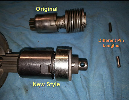
The starter had a bad bendix drive which uses centrifugal force to engage/dis-engage the starter drive with flywheel teeth. The new replacements seem to work fine but are tough to get installed on the starter shaft. The mounting ring was so hard to pull back, I built a special jig to insert the shaft pin.
The goal was to have larger flat surface areas to more effectively grip with C-clamps or vises. The rounded edges on the bendix starter drives offered very little gripping surfaces. I used small pieces of angle iron bolted together (to prevent the pieces from coming apart) and then external C-clamps to pull-back the spring-mounted cover plate in order to install the shaft pin. It looks clumsy and took a couple of hours to make; but it sure made this process much easier! And the new style starter drives are easier to slip past the flywheel when installing the completed starter assembly back into the engine block.


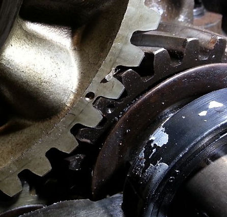
The Flywheel
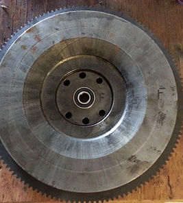
It needed a new ring gear as the teeth were slightly worn in a few spots. Overall, it actually didn't look too bad but I'm glad a new one is installed. I don't have a torch so I took it to my favorite machine shop. They removed the old one and installed the new one (getting it really hot) in about an hour.
The image on the left is before the pilot bearing was replaced, middle image is with new pilot bearing. Far right image is with flywheel installed on mounted drive shaft. While the surface looks somewhat worn, it's cosmetic only. There was no pitting or scars after a general cleanup. The clutch works quite well.


Oil Pump
The gears and teeth all looked good but the bushing was quite worn creating a very wobbly spin to the drive gear. The image on the left shows the old (worn) bushing setting on the bench: notice the right-side is much thinner. The new bushing is installed in this view.
The image on the right shows using a vise to drive in the new bushing. Take your time with this and make sure it's perpendicular. I had to do some minor sanding (rolled up piece of 300- grit sandpaper) to let the original gear drive shaft fit and spin with reasonable resistance.


The Oil Pickup Tube
Ford N-series tractors are remarkably well-designed: except for the oil pickup tube. What were the engineers smoking? This part must perform two tasks:
1) Pickup oil from the crankcase and allow flow to the oil pump
2) Provide coarse filtering through a screen mesh
The main issues with the design are:
A) Extremely heavy 'bell' at end of pickup tube:
- Creates a tremendous amount of stress at oil pump mounting point which is only soldered/brazed into cast metal.
- Don't think it's heavy? Try holding the oil-pump end of the pickup tube using two fingers gripping 1/2" of the pipe for a grip: that's the problem.
- Very annoying to align the bell to fit inside the mesh filter on the crankcase drain oil plug. It's really crazy.
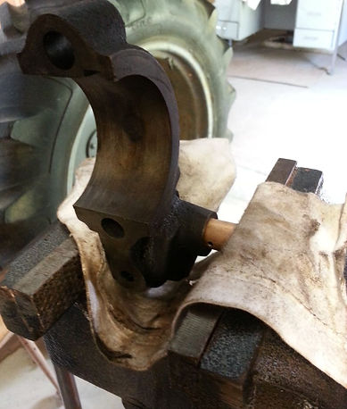
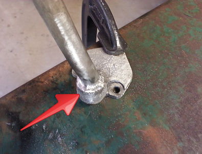
B) Poor mounting technique (left image):
- The oil pump is cast iron and the pickup tube (steel, sometimes aluminum) is ONLY silver-soldered (or brazed) into cast iron: that doesn't work.
- Engine vibration causes the brazing to crack and allows the pump to 'suck air' instead of oil resulting in declining oil pressure: not good for any engine.
C) Inadequate screen filtering (right image):
- Even when perfectly aligned, there is a HUGE gap between the screen filter and the end of the pickup tube: tons of room for debris to enter the pump.
- The gap is 1/2" and tapers down around perimeter: a rough calculation of "unfiltered" open area for debris to enter? About the size of a silver dollar.
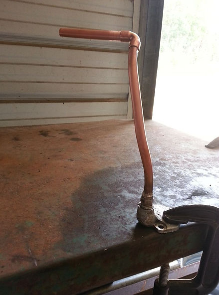
The Modified Oil Pickup Tube
I re-designed the oil pump with about $5 in parts and all of the above concerns are addressed. The results so far=excellent!
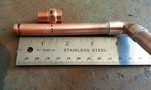
Firist, I cut about 10" of 1/2" Copper Pipe, Type L which is suited for fuel, fuel oil, etc. I noticed the orifice of the two oil pump assemblies are less than 1/2" diameter so 1/2" ID for a pickup tube is plenty large enough. See left image.
Then you can start by gently bending the 1/2" copper pipe to match the general shape of the original design; see right image. Take your time.
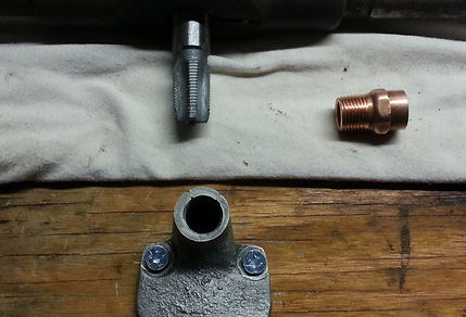
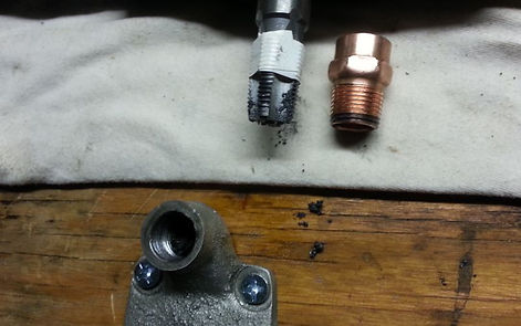
To solve the brazing/silver-solder issue not adhering to cast iron, I tapped NPT threads into the oil pump assembly. Was very easy to do. Now we have a very solid mechanical mount. To prevent oil from wicking through up the threads I heated the threads and let solder flow down them filling all voids AFTER I installed the adapter into the cast iron oil pump base. The solder won't stick to the cast iron, we are only using it as a filler material to seal the threads.
Next I made the 90 degree turn to replace the clunky bell: I still that's the goofiest design I've every seen... anyway. Match the profile of the turn from the original part. Solder a right-angle copper piece into place; make sure this solder connection is air-tight (I mean, oil-tight).
The image on the left shows Sharpie marks on the copper pipe indicating approximate lengths to accomodate the new metal mesh filter design.
The image to the left shows thereplacement copper pipe assembly mounted to the oil pump face plate. The image to the right shows the new filter screen (cut from the oil drain plug screen) and soldered over the 1/2" threaded pipe adapter. No dirty oil can sneak past this design.
Here is a view of the installed replacement oil pickup tube assembly to the left. I'm holding the original pickup tube design (it's very heavy holding it like this, too further emphasing the tremendous stress put on the original silver solder/brazed joint.
I was extremely delighted with the final design: it overcomes all the obvious faults with the design from long ago. Some people may be OK with this approach as it did work fairly well all these years. However, it is also known that the oil pickup tubes do fail (crack) around the mounting plate causing oil pressure to slowly drop over time. This design prevents that from ever happening.
The image to the right is how well the end of the new pickup tube is centered in the oil drain opening: awesome. No more fooling around trying to get the screen aligned with the original pickup tube bell: that's just a crazy concept.
A final view. This side photo gives another perspective on this modification. Copper piping threaded into the mounting block, silver soldered to seal the threads, a much-lighter overall assembly and a screen that does not allow dirty oil to bypass. And no alignment hassles when you install the crankcase cover. Turning over the crankshaft a few times will ensure the modified oil pickup tube has no clearance issues with a running engine.
It's worked very well so far; my oil pressure is ~60 PSI. All for about $5 in parts a about 3-4 hours of fabrication. It was a fun engine lubrication upgrade!

The Carburetor
I used an existing procedure and modified it along way to rebuild the carburetor. You can get the procedure from Kevin LaRue via his awesome website:
http://www.myfordtractors.com/index.shtml
It's an interesting website and became my motivation to document my restoration efforts. Hats off to Kevin!
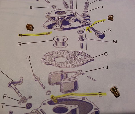
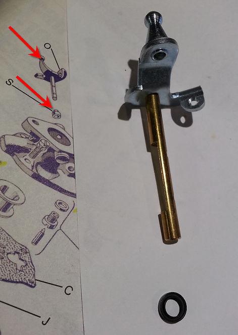
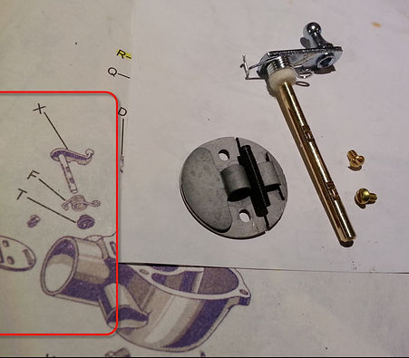
I used some old electric guitar string taking advantage of the 6 various string sizes to clear out the various carb ports and passages. Kevin's carb rebuild procedure is awesome. Here is how mine turned out:
The one thing I will add are photos I took of the physical rebuild kit parts as compared to exploded illustrated parts drawings. This helped me associate real-world parts to illustrated parts diagrams as follows: pictures are in no particular order.


Timing is Everything
It takes air, gas, and spark to start an engine... if the spark is strong enough. And if the gas isn't old. And if the air-gas mixture is correct. Oh, and yes, IF all of this happens at the right time. As you can see, it's not that simple. So remove timing doubts by ensuring these two things:
A) Left Image - Timing marks lined up together B) At this setting, all cylinders are 1/2 in travel (beer cans are visual aid)

Cylinder Head Gasket
I used the "all metal" cylinder head gasket with the spray-on copper sealant. The one with the metal rings around it (red arrow) did not support adequate compression. I was really impressed with the compression numbers after using the all-metal gasket and this stuff.

